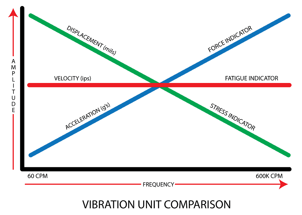
Vibration analysis is one of the most effective tools for identifying mechanical and/or electrical faults in rotating machinery early to take action before a costly failure occurs. The three main parameters measured to evaluate the vibration characteristics of a piece of equipment are acceleration, displacement, and velocity. To gain a better understanding of the insights these parameters provide an analyst, let’s take a deeper dive into each one individually and the tools commonly used to measure them.
Acceleration
Acceleration refers to the change in velocity with respect to time; it is an indication of the force of vibration.
Frequencies emphasized: High frequencies – above 60,000 cycles per minute (CPM)
Transducers commonly used: piezoelectric accelerometers
A piezoelectric accelerometer (Figure 1) uses the piezoelectric effect (ability to generate an electric charge in response to applied mechanical stress) to measure changes in acceleration, pressure, strain, temperature or force by converting energy into electrical charge.
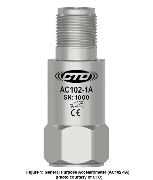
While there is an abundance of accelerometers from which to choose based on the particulars of the situation, typical characteristics include:
- Dynamic events only (>0.5 HZ)
- Wide dynamic range (>120 dB = 1,000,000:1)
- Wide bandwidth (>10 kHz)
- Self-generating sensing element
- Operates over two wires
- Rugged (5000 g survivability)
- High-Temperature Charge Versions
Common configurations:
- Compression mode
- Flexural mode
- Shear mode
Typical measurement units:
- g’s (Everything on the Earth’s surface at sea level experiences 1 g of downward acceleration)
- Inches per second
- Meters per second
Acceleration is typically effective at identifying:
- Early bearing faults
- Gear faults
- Pumps and compressors (e.g. cavitation and turbulence)
Displacement
Displacement refers to the amount/distance a vibrating object moves from its original position.
Frequencies emphasized: Low frequency – (less than 600 CPM)
Transducers commonly used: Proximity probes
Damping is necessary for rotating equipment to prevent vibrations from damaging the rotor, bearing, and other components. Fluid film bearings (also referred to as journal or sleeve bearings), often found on critical turbomachinery, have significantly more damping than rolling element bearings. This high damping often causes machinery equipped with sleeve bearings not to transmit shaft vibration to the bearing housing very well – especially in machinery with light rotors and massive bearing housing and supports. For this reason, proximity probes are the industry standard for measuring vibration levels on sleeve bearings.
Proximity probes are sensors that measure relative displacement (mils) between of the bearing housing and shaft. Normal measurement involves two radial proximity probes (X & Y) installed 90 degrees apart at each bearing. Figure 2 below is a magnified animation of a proximity probe set up on a journal bearing.
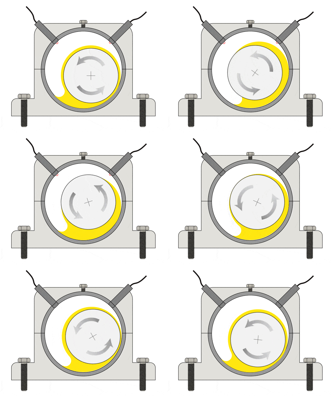
Figure 2: Proximity Probes/Journal Bearing
Mounting options:
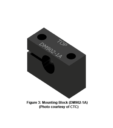
- Internal mounting – This refers to the mounting of eddy current probes completely inside the machine or bearing housing with blocks like the one pictured in Figure 3 Mounting in this way allows the probe to measure the shaft surface, minimizes installation costs, and offers very precise measurement of the shaft position and vibration.
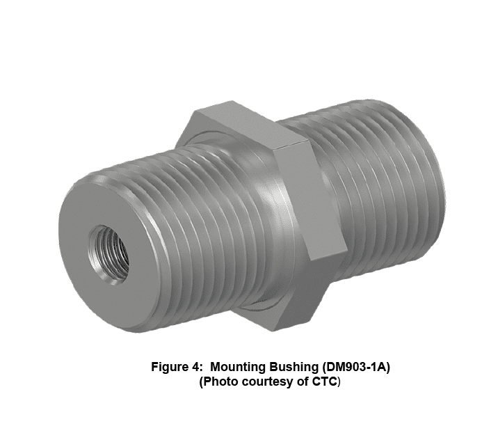
- Through mounting – Also known as “internal/external” mounting refers to mounting the probe through the bearing casing using a mounting adapter bushing like the one pictured in below (Figure 4). The casing is counter bored to prevent the probe from side sensing or providing false readings from the bearing housing. This allows external access to the probe while also allowing the probe tip to be internal to the bearing housing or machine.
- Reverse mount housing – This type of mounting is generally used when other methods aren’t available. Special care must be given to the quality of the shaft surface and the mechanical protection of the exposed probes and cables. This type of mounting offers easy access to the probes and low installation costs. However, exposed areas of the shaft may experience scruffing, scratching, or rust which limits the measurement quality of the probes.
Typical measurement units: Mils (1/1000 inch) peak to peak
Displacement is typically effective at identifying:
- Misalignment
- Resonance
- Loose bolts
- Structural problems
Displacement measurements are typically used when examining the “big picture” of mechanical vibrations. For example, you might use displacement to confirm suspected unbalance in a rotating part due to a considerable amount of movement at the rotational frequencies of the shaft.
Velocity
Velocity refers to the speed that an object is moving during its oscillations; it is a measure of energy dissipated and the consequent fatigue of machine components. Velocity measurement is most often used when important frequencies lie in the mid-frequency range. Since a wide variety of machinery defects occur in this range, velocity is the amplitude unit most commonly used for condition monitoring and trending.
Frequencies emphasized: Mid-range (between 600 CPM – 60,000 CPM)
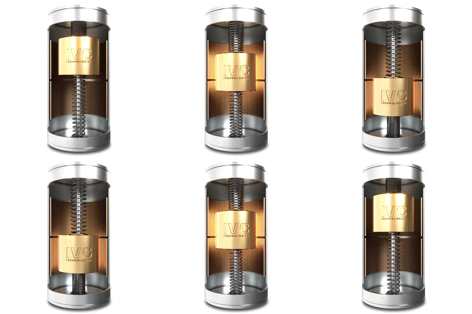
- True velocity sensor – Consists of a large case with a mass that moves through a coil and generates its own signal and is very good for lower frequency measurements. Animation below (Figure 5).
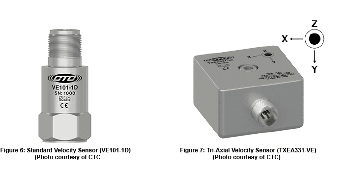
- Velometer – Essentially a standard ICP-type accelerometer with an analog integration circuit inside that converts the signal to a velocity signal. Examples (Figures 6 & 7) below:
Typical measurement units: Velocity is measured in peak units such as inches per second or millimeters per second. The root mean squared (RMS) value of velocity is calculated by multiplying peak amplitude by 0.707.
Velocity is typically effective at identifying: Unlike acceleration and displacement which are said to be “frequency dependent” meaning the amount present of each is dependent on whether the frequency range is high (acceleration) or low (displacement). Because velocity covers a wide frequency range, it is a powerful tool for assessing the severity of an identified machine fault.
Acceleration, displacement, and velocity each prioritize certain frequency ranges in their own way. When analyzed together, they provide critical information for diagnosing the cause of excessive vibration.
Up next month: “How to Choose the Ideal Accelerometer for Your Application.
