The use of Variable Frequency Drives (VFDs) to control AC motors has increased dramatically in recent years. However, it doesn’t come without risks.
The challenge with VFDs is the potentially damaging electrical current that is caused by a buildup of voltage along the rotating motor shaft. As the voltage accumulates on the shaft, it seeks the path of least resistance to the ground, which typically is the bearing or seal closest to the shaft.
One of the first “symptoms” of bearing current damage is audible bearing noise. Unfortunately, by the time the bearing noise is noticeable, deterioration due to Electrical Discharge Machining (EDM) damage has already developed to the point that catastrophic bearing failure is not far behind.
Vibration Analysis and Shaft-to-Ground Voltage/Current Analysis
Currently, there are two types of non-destructive testing methods commonly used to identify bearing currents and resulting damage: vibration analysis and shaft-to-ground voltage/current analysis. While these methods can be implemented for the specific purpose of confirming the presence of bearing current, there are significant advantages with incorporating these methods into a regular maintenance program. By doing so, a baseline can be established and trends can be closely monitored, thereby providing early detection of any issues.
It is important to note that both vibration analysis and shaft-to-ground voltage/current analysis require highly specialized equipment and should therefore be conducted by an experienced professional familiar with the equipment as well as data analysis. Massive amounts of data are of no use if not interpreted correctly.
Vibration Analysis
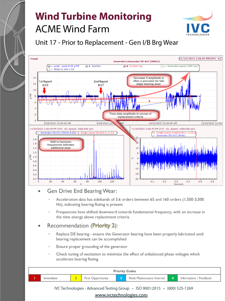
Vibration analysis is an effective tool for detecting fluting damage to a bearing caused by EDM. In the early stages of fluting damage, the high frequency, high-resolution spectrum of a bearing will reveal a cluster of energy in the 2-4 kHz frequency range. As the bearing continues to deteriorate, the fault energy spikes will migrate into lower bearing fault frequencies. This is an excellent example of the benefit of having continuous monitoring of vibration levels in place beginning shortly after installation. The appearance of atypical increases or changes in energy spikes has a better chance of being detected early if there is a baseline with which to compare it against. Figure 1 below is an example of fluting detected from wind turbine remote analysis.

Figure 1: Data showing indication of fluting obtained during wind turbine remote analysis
Voltage and Current Analysis
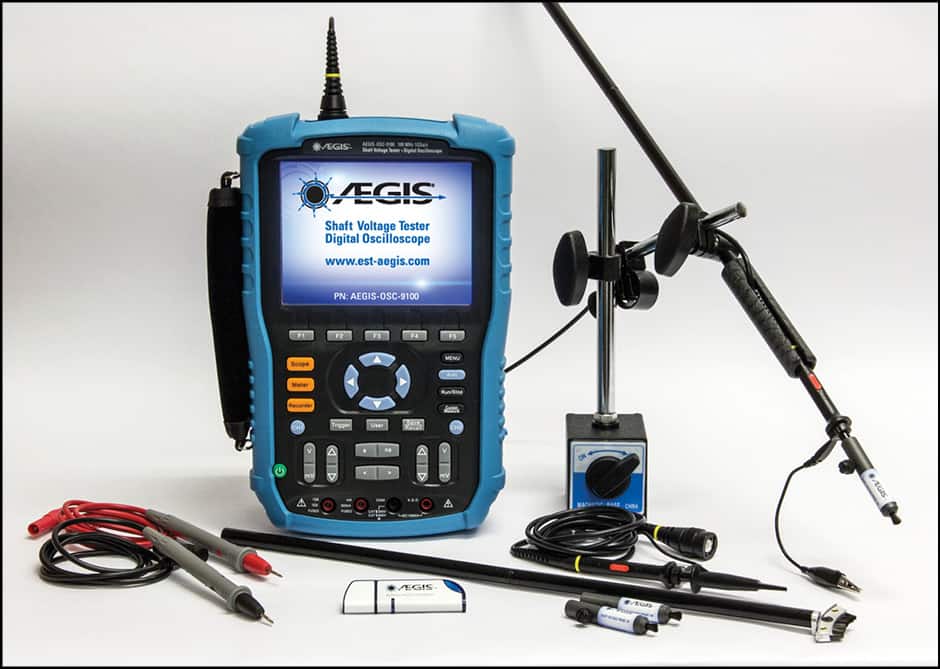
Measuring the actual voltage and current present on a shaft is extremely helpful when attempting to confirm the presence of EDM damage. Shaft voltage testing can clearly determine whether or not capacitive discharge current is flowing through the bearing. This is done using a shaft voltage tester such as the one pictured in Figure 2 below from AEGIS®. The device measures the potential difference between the motor shaft and frame which will be equal to the voltage across the bearing.

Figure 2: AEGIS Shaft Voltage Tester – Image courtesy of Electro Static Technology (AEGIS®)
To conduct current analysis using an electrical discharge detector, an average of the electrical flux generated around the motor casing is taken in 30-second intervals. Once a value is acquired, a determination can be made as to whether the electric current passing through the bearing is causing the defect. It should be noted that electrical discharge detectors are most reliable when used with high-power motors over 100 HP.
There are three types of electrical currents induced along the motor shaft in a VFD: Capacitive Current, High-Frequency Current, and Rotor Ground Current.
Capacitive Discharge Current
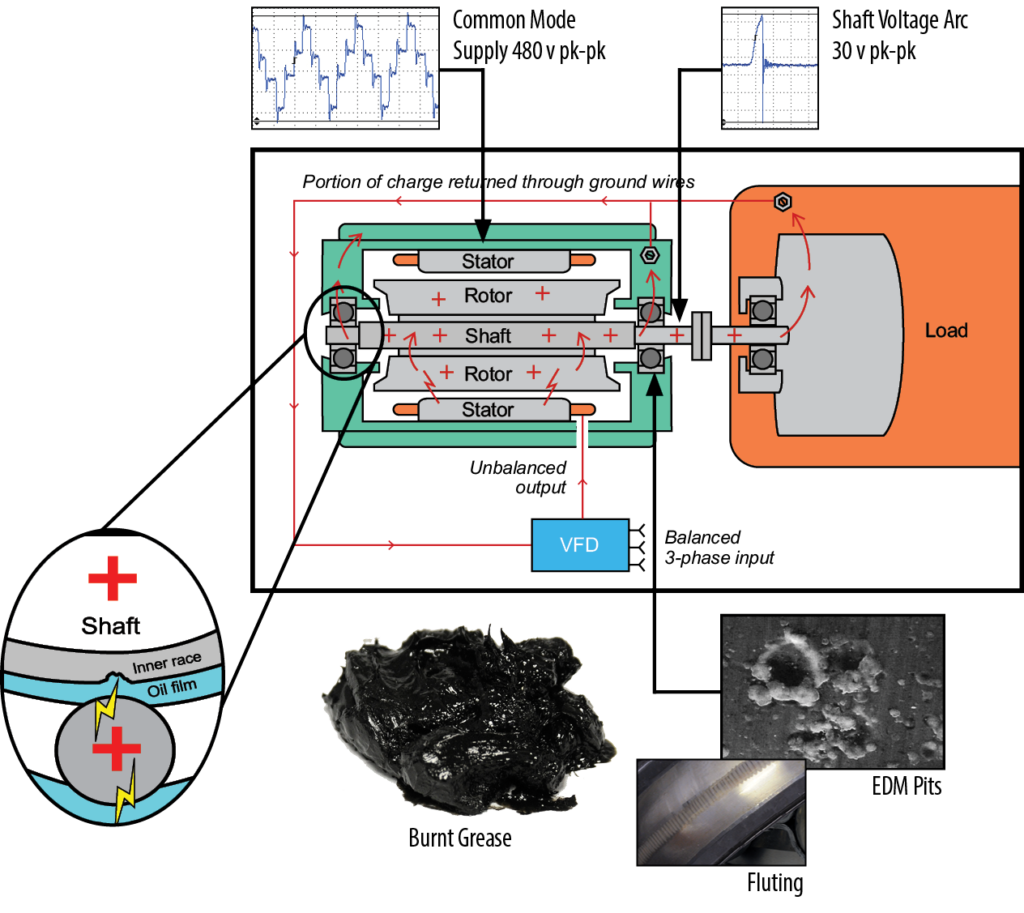
In a capacitator, energy is stored by having two conductive plates with opposite polarization sandwiched around an insulator. In the case of a motor, the rotor and stator generate capacitive current EDM due to their close proximity, polarization, and the air acting as the insulator. See Figure 3 below.

Figure 3: Capacitive Discharge Current – Image courtesy of Electro Static Technology (AEGIS®)
High-Frequency Circulating Current
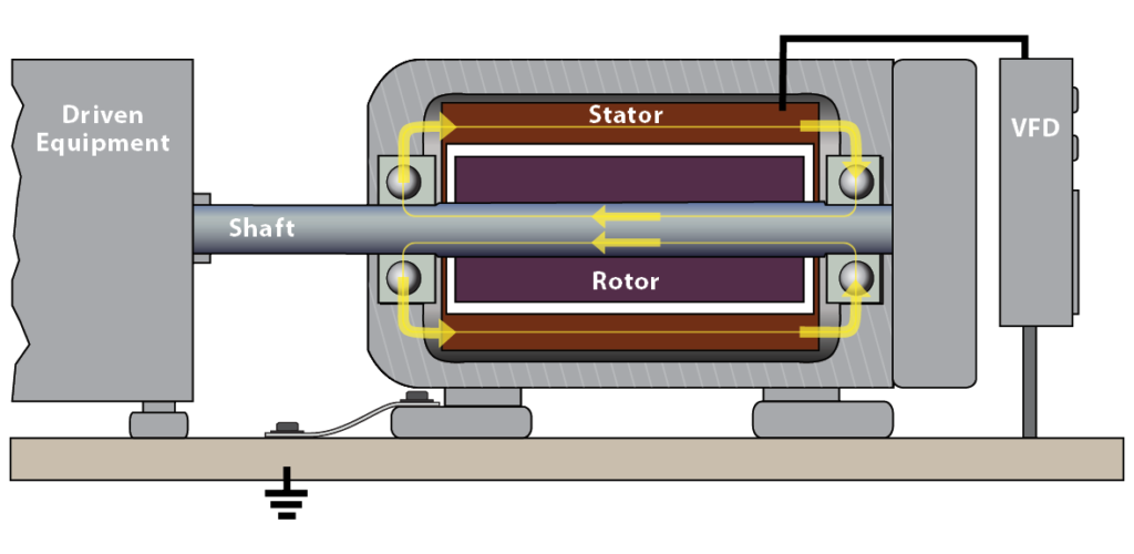
All VFD-involved bearing currents involve high frequencies. Whereas the capacitive current discharges in one direction – from shaft to frame or frame to shaft, the high frequency circulating current travels in opposite directions across each bearing simultaneously; from frame to shaft at one bearing and shaft to frame at the other. Charge flows onto the shaft at one end and off of the shaft at the other, in a roughly circular pattern. See Figure 4 below.

Figure 4: High-Frequency Circulating Current – Image courtesy of Electro Static Technology (AEGIS®)
Rotor Ground Current
In short, this type of current is a lot like the capacitive current. However, it is only a problem when the motor frame is poorly grounded.
It should be noted that since all motors have some level of shaft voltage, it is critical to determine at what level, once reached, would be cause for alarm. The difficulty lies in the fact that predicting EDM damage is not an exact science. There is no “industry standard value” that can be applied to all machines to determine whether a particular machine is “safe” from EDM damage. Additionally, there are many variables that must be taken into consideration when determining an alarm level including but not limited to running speed, bearing lubrication, measurement equipment, and method.
To repeat, there is great value in trending the correct measurement values amidst so many other indicators. Measurement and trending of shaft voltage/current data can lead to early identification of EDM damage. Early identification means planning the right maintenance on the right location at the right time.
Up next: In the final segment on VFDs and EDM, we’ll take a closer look at factors that contribute to/exacerbate EDM as well as how you can protect against EDM damage.
